
Example 3.5: Graphical static analysis of a four-bar linkage#
A horizontal force \(\vec{P}\) of \(100\) N, pointing to the left, acts at point \(C\) of the rocker of the four-bar linkage in the figure. Compute graphically the reactions at the four joints and the torque \(M_2\) to be applied to the crank to keep the mechanism in equilibrium at this position. The masses of the links and friction are neglected.
Data: \(\overline{O_2A} = 0.20\) m, \(\overline{AB} = 0.50\) m, \(\overline{O_4B} = 0.35\) m, \(\overline{O_2O_4} = 0.45\) m (horizontal), \(\overline{O_4C} = 0.25\) m, \(\theta_2 = 45^\circ\).
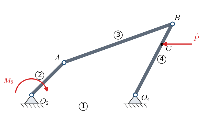
Solution
Position. From the position analysis (for instance, drawing to scale with ruler and compass): \(A = (0.1414, 0.1414)\) m, \(B = (0.6121, 0.3102)\) m, and \(C\), \(0.25\) m from \(O_4\) along \(O_4B\), at \((0.5658, 0.2216)\) m. The coupler is at \(19.7^\circ\) from the horizontal.
Link 3 (coupler). It only receives forces at its two joints: it is a two-force member, so \(\vec{F}_{34}\) (the force of the coupler on the rocker) acts along \(AB\).
Link 4 (rocker). It is a three-force member: \(\vec{P}\), known; \(\vec{F}_{34}\), along \(AB\); and \(\vec{F}_{14}\), through \(O_4\) with unknown line of action. The three must meet at a point:
Extend the line of action of \(\vec{P}\) (horizontal through \(C\)) and line \(AB\). They meet at \(Q = (0.3649, 0.2216)\) m.
\(\vec{F}_{14}\) must go through \(O_4\) and \(Q\): its line of action is now known (\(-69.0^\circ\)).
Draw \(\vec{P}\) to scale and, from its ends, lines parallel to \(AB\) and to \(O_4Q\). The closed triangle \(\vec{P} + \vec{F}_{34} + \vec{F}_{14} = \vec{0}\) gives the magnitudes and senses:
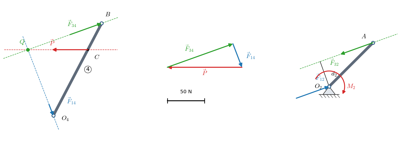
\(\vec{F}_{34}\) points from \(A\) towards \(B\): the coupler pushes the rocker, it works in compression.
Link 2 (crank). The coupler exerts \(\vec{F}_{32} = -\vec{F}_{34} = 93.4~\text{N}\angle{-160.3^\circ}\) on the crank, at \(A\). For force equilibrium, \(\vec{F}_{12} = -\vec{F}_{32} = 93.4~\text{N}\angle 19.7^\circ\). Both forces are parallel and opposite, and form a couple of value \(|\vec{F}_{32}|\, d_2\), where \(d_2 = 0.0854\) m is the distance from \(O_2\) to line \(AB\) (measured on the drawing). The torque \(M_2\) must balance it:
The sense follows from noting that \(\vec{F}_{32}\), applied at \(A\) and pointing down and to the left, tends to turn the crank counterclockwise about \(O_2\); the input torque must be clockwise.
Ground. It receives \(\vec{F}_{21} = -\vec{F}_{12}\) at \(O_2\) and \(\vec{F}_{41} = -\vec{F}_{14}\) at \(O_4\). Their resultant equals \(\vec{P}\) (the external load is transmitted to the ground), and the moment they produce, together with \(M_2\), is the moment the anchors must withstand.
Analytical check. By the principle of virtual power (lesson 4), \(M_2\,\omega_2 + \vec{P}\cdot\vec{v}_C = 0\) for any compatible velocity. With \(\omega_2 = 1\) rad/s, the velocity analysis gives \(\omega_4 = 0.360\) rad/s and \(\vec{v}_C = \vec{\omega}_4\times\vec{r}_{O_4C} = (-0.0797, 0.0416)\) m/s, so \(M_2 = -\vec{P}\cdot\vec{v}_C/\omega_2 = -7.97\) N·m (clockwise). ✓