
Example 2.4: Kinematic analysis of an inverted slider-crank mechanism#
Position analysis#
The figure shows an inverted slider-crank mechanism. At the instant when the crank forms an angle \(\theta_2 = 60^{\circ}\) with the horizontal, calculate the position of the slider with respect to point A, the angles that links 3 and 4 form with the horizontal, and the coordinates of point C.
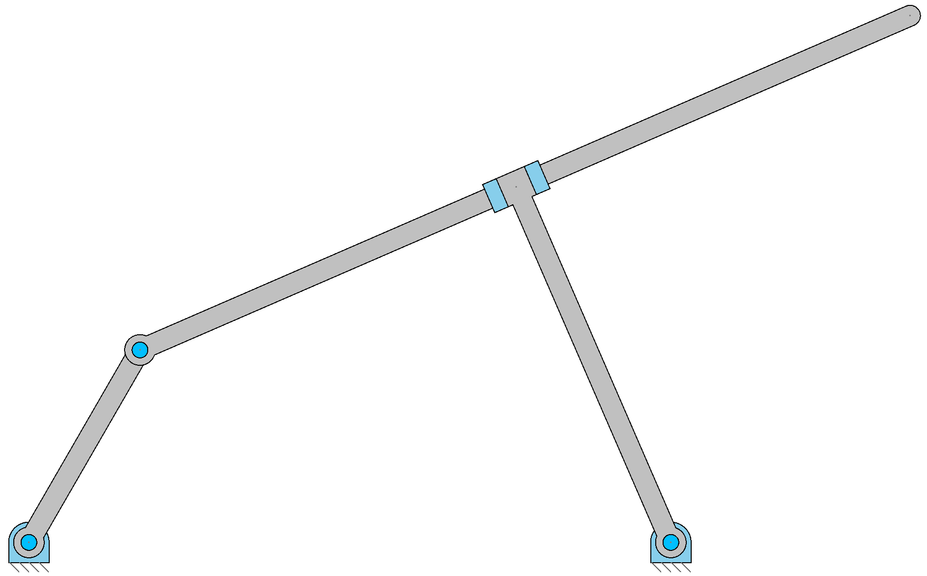
Data:
Link lengths, in meters: \(\overline{O_2 A} = 0.45;\, \overline{AC} = 1.7;\, \overline{O_4B} = 0.7855;\, \overline{O_2O_4} = L_1 = 1.30 \text{ m};\) the angle \(\gamma\) that links 3 and 4 form is \(90^\circ\).
Position analysis: graphical method#
The objective is to construct the mechanism to scale to measure the unknowns: the distance of the slider to point A (\(\overline{AB}\)), the angles \(\theta_3\) and \(\theta_4\), and the coordinates of point C.
Construction Data:#
Link 1 (Frame): Distance \(\overline{O_2O_4} = L_1 = 1.30 \text{ m}\)
Link 2 (Crank): \(L_2 = \overline{O_2A} = 0.45 \text{ m}\).
Link 3 (Coupler): Point C is at a distance \(\overline{AC} = 1.7 \text{ m}\) from A.
Link 4 (Rocker): The perpendicular distance from \(O_4\) to the slot is \(h = \overline{O_4B} = 0.7855 \text{ m}\).
Input Angle: \(\theta_2 = 60^\circ\).
Geometric Constraint: The angle between the line \(AC\) (link 3) and the line \(O_4B\) (link 4) is \(90^\circ\).
Construction Procedure:#
Establish the frame: Locate pivot \(O_2\) at the origin (0,0) and pivot \(O_4\) at \((L_1, 0)\).
Position the crank: Draw link 2 from \(O_2\) with length \(L_2=0.45\) and angle \(\theta_2=60^\circ\) to find point A.
Draw the slot (Link 3):
Draw a circle with center \(O_4\) and radius \(h = 0.7855\).
Draw a straight line starting from A and tangent to this circle. This defines the direction of link 3 and its angle \(\theta_3\). There are two possible tangents, choose the one corresponding to the figure.
Locate point B: Point B is the point of tangency between the line and the circle.
Locate point C: On the line passing through A and B, measure a distance \(\overline{AC} = 1.7\) from A to find C.
Determine link 4: Draw the line connecting \(O_4\) and B. Its angle is \(\theta_4\).
Measurement of results: Measure from the drawing the distance \(\overline{AB}\), the angles \(\theta_3\) and \(\theta_4\), and the coordinates of C.
Position analysis: analytical method#
Vector Loop Formulation#
We consider the triangle formed by points \(O_2, O_4, A\). The distance between \(O_4\) and A, \(d_{O_4A}\), can be calculated with the law of cosines: \( d_{O_4A}^2 = L_1^2 + L_2^2 - 2L_1L_2\cos\theta_2 \) In the right triangle \(O_4BA\), we have: \( d_{O_4A}^2 = (\overline{O_4B})^2 + (\overline{AB})^2 = h^2 + (\overline{AB})^2 \) Equating both expressions, we can solve for the distance \(\overline{AB}\) (position of the slider with respect to A): \( \overline{AB} = \sqrt{L_1^2 + L_2^2 - 2L_1L_2\cos\theta_2 - h^2} \)
Solving for \(\theta_3\) and \(\theta_4\)#
Calculate angle \(\alpha = \angle AO_4O_2\): Using the law of sines in triangle \(O_2O_4A\): \( \frac{\sin\alpha}{L_2} = \frac{\sin\theta_2}{d_{O_4A}} \implies \alpha = \arcsin\left(\frac{L_2\sin\theta_2}{d_{O_4A}}\right) \)
Calculate angle \(\beta = \angle AO_4B\): Using the right triangle \(O_4BA\): \( \cos\beta = \frac{\overline{O_4B}}{d_{O_4A}} = \frac{h}{d_{O_4A}} \implies \beta = \arccos\left(\frac{h}{d_{O_4A}}\right) \)
Calculate \(\theta_3\) and \(\theta_4\): Observing the geometry of the mechanism: \( \theta_3 = 180^\circ - (\alpha + \beta) \) Since \(\vec{O_4B}\) is perpendicular to the line AC (link 3): \( \theta_4 = \theta_3 - 90^\circ \)
Calculation of the Coordinates of Point C#
\( \vec{R}_C = \vec{R}_A + \vec{R}_{AC} \)
\(x_C = L_2\cos\theta_2 + \overline{AC}\cos\theta_3\)
\(y_C = L_2\sin\theta_2 + \overline{AC}\sin\theta_3\)
Numerical Calculation#
Initial Data:
\(L_1 = 1.3 \text{ m}\)
\(L_2 = 0.45 \text{ m}\)
\(\overline{AC} = 1.7 \text{ m}\)
\(h = \overline{O_4B} = 0.7855 \text{ m}\)
\(\theta_2 = 60^\circ\)
1. Calculate distance \(d_{O_4A}\) and slider position \(\overline{AB}\): \( d_{O_4A}^2 = 1.3^2 + 0.45^2 - 2(1.3)(0.45)\cos(60^\circ) = 1.69 + 0.2025 - 0.585 = 1.3075 \) \( d_{O_4A} = \sqrt{1.3075} \approx 1.143 \text{ m} \) \( \overline{AB} = \sqrt{d_{O_4A}^2 - h^2} = \sqrt{1.3075 - 0.7855^2} = \sqrt{0.6904} \approx 0.831 \text{ m} \)
2. Calculate angle of vector \(\vec{R}_{O_4A}\) (\(\phi\)) and angle \(\beta\): The angle \(\phi\) is that of the vector from \(O_4\) to A. \( \phi = \arctan\left(\frac{y_A - y_{O_4}}{x_A - x_{O_4}}\right) = \arctan\left(\frac{L_2\sin\theta_2}{L_2\cos\theta_2 - L_1}\right) = \arctan\left(\frac{0.45\sin(60^\circ)}{0.45\cos(60^\circ) - 1.3}\right) \) \( \phi = \arctan\left(\frac{0.3897}{-1.075}\right) \approx 160.05^\circ \) The angle \(\beta\) is from the right triangle \(O_4BA\). \( \beta = \arccos\left(\frac{h}{d_{O_4A}}\right) = \arccos\left(\frac{0.7855}{1.143}\right) \approx 46.59^\circ \)
3. Calculate \(\theta_3\) and \(\theta_4\): From the geometry, it is observed that the angle of link 4, \(\theta_4\), is the sum of angles \(\phi\) and \(\beta\) (considering the quadrant). The configuration in the figure corresponds to: \( \theta_4 = \phi - \beta = 160.05^\circ - 46.59^\circ = 113.46^\circ \) And the angle of link 3 (the slot) is perpendicular to link 4: \( \theta_3 = \theta_4 - 90^\circ = 113.46^\circ - 90^\circ = 23.46^\circ \)
4. Calculate Coordinates of Point C: \( x_C = L_2\cos\theta_2 + \overline{AC}\cos\theta_3 = 0.45\cos(60^\circ) + 1.7\cos(23.46^\circ) = 0.225 + 1.559 = 1.784 \text{ m} \) \( y_C = L_2\sin\theta_2 + \overline{AC}\sin\theta_3 = 0.45\sin(60^\circ) + 1.7\sin(23.46^\circ) = 0.3897 + 0.677 = 1.067 \text{ m} \)
Final Position Results:
Slider position: \(\mathbf{\overline{AB} = 0.831 \text{ m}}\)
Angle of link 3: \(\mathbf{\theta_3 = 23.46^\circ}\)
Angle of link 4: \(\mathbf{\theta_4 = 113.46^\circ}\)
Coordinates of C: (1.784, 1.067) m