
Ctrl+K

Machine and Mechanism Theory

  • Ver en Español

Course contents:

  • Lesson 1: Basic concepts on Mechanisms
    • Definitions
    • Links and joints: detailed classification
    • Four-bar linkage
    • Six-bar linkage
    • Other well-known mechanisms
    • Determining the d.o.f. count
    • DOF solved problems
    • Problems: Determine the kinematic chain
  • Lesson 2: Kinematic Analysis
    • Introduction to Kinematic Analysis
    • Position Analysis
    • Velocity Analysis
    • Acceleration Analysis
    • Solved examples
      • Example 2.1: Kinematic analysis of a four-bar linkage
      • Example 2.2: Kinematic analysis of a slider-crank mechanism
      • Example 2.3: Kinematic analysis of a quick-return mechanism
      • Example 2.4: Kinematic analysis of an inverted slider-crank mechanism
      • Example 2.5: Kinematic analysis of a six-bar linkage
      • Example 2.6: 2026 exam, exercise 3
      • Example 2.7: Bar with two sliders
      • Example 2.8: Two bars with two sliders
      • Example 2.9: Bicycle suspension
      • Example 2.10: Disc with a sliding collar
      • Example 2.11: Rocker with a pin in a rotating slot
      • Example 2.12: Thumb motion (3D relative motion)
      • Example 2.13: Carousel horse (3D relative motion)
  • Lesson 3: Dynamics
    • Introduction to Dynamic Analysis of Mechanisms
    • Example 3.1
    • Example 3.2
    • Particle dynamics
  • Lesson 4: Work and Energy
    • Lesson 4: Basic Concepts of Work and Energy Applied to Mechanisms
    • Lesson 4: Application Examples (Work, MA and Passive Resistances)
  • Lesson 5: Fundamentals of Machine Balancing
    • Lesson 5: Fundamentals of Machine Balancing
    • Example 5.01: Dynamic Balancing
  • Lesson 6: Introduction to Mechanism Synthesis
    • Lesson 6: Introduction to Mechanism Synthesis
    • Example 6.1
  • Lesson 7: Gear Theory
    • Introduction: Fundamentals of Gear Transmission
    • The Interference Phenomenon
    • Velocity Ratio and Number of Teeth: the Continued-Fraction Method
    • Gear Typology
    • Gear Manufacturing
  • Lesson 8: Gear Trains
    • Introduction and Prerequisite Concepts
    • Epicyclic (Planetary) Gear Trains
  • Lesson 9: Kinematics of Robots
    • Rotation and translation transformations
    • Robot Forward Kinematics Simulator
  • Bibliography
  • Credits
  • .md

Links and joints: detailed classification

Contents

  • Types of closure in kinematic pairs
  • Classification of links
  • Classification of pairs by degree of freedom

Links and joints: detailed classification#

Types of closure in kinematic pairs#

For a joint to work, contact between the links must be guaranteed. This can be achieved in three ways:

  • Form closure: Contact is ensured by the geometry of the two members of the pair itself (e.g. cylinder-piston).

  • Force closure: Contact is ensured by the force exerted by an external element, such as a spring (e.g. cam-follower).

  • Chain closure: Contact is ensured by means of another member of the same mechanism (e.g. meshing of two gear wheels).
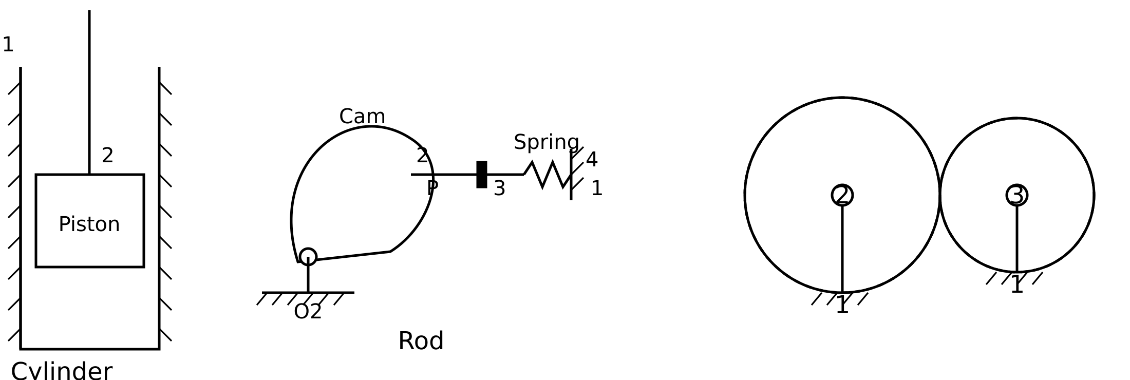
    chain closure

Classification of links#

By material behavior:

  • Rigid: Assumed not to deform. This is the main assumption in this course.

  • Elastic: Their deformation is relevant (e.g. springs, flexible beams).

  • Fluid: The link is a fluid (e.g. hydraulic cylinder).

By type of motion (in four-bar mechanisms):

  • Crank: If it can make full turns (360°) about a fixed axis.

  • Rocker: If it rotates about a fixed axis but without completing full turns.

  • Connecting rod or coupler: A link with no end connected to the ground.

  • Slider: Slides along a guide.

Classification of pairs by degree of freedom#

The degree of a kinematic pair is the number of degrees of freedom it allows in the relative motion.

Degree I pairs (1 d.o.f.) A point of the moving link traces a curve. degree I pairs
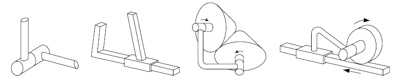
  • Revolute or pin joint: (R)

  • Prismatic or slider: (P)

  • Helical: (H)

Degree II pairs (2 d.o.f.) A point of the moving link traces a surface.

  • Cylindrical: (C)

  • Rotation + Translation:

Degree III pairs (3 d.o.f.) A point of the moving link traces a volume.

  • Spherical or ball joint: (S)

  • Planar: (Pl)

previous

Definitions

next

Four-bar linkage

Contents
  • Types of closure in kinematic pairs
  • Classification of links
  • Classification of pairs by degree of freedom

By Mechanical Engineering, University of Almería

© Copyright 2022-2026, Mechanical Engineering, University of Almería.