
Definitions#
The study of mechanisms is the first fundamental step for the design and analysis of any machine. Before being able to understand the forces or the driving torque a machine needs (dynamic analysis), it is essential to understand its motion. Kinematic analysis focuses on the geometry of that motion, allowing us to determine the position, velocity, and acceleration of each component. This analysis is, therefore, the pillar on which the whole of mechanical design is built. To tackle the kinematic analysis of mechanisms, we first need to be familiar with a series of definitions covered in the following sections.
Machines vs Mechanisms#
Machine
Set of bodies, put together such that they have relative motion and transmit forces from a power source to a place where work needs to be done.
An alternative definition describes it as:
A combination of resistant bodies arranged to make the mechanical forces of nature do work accompanied by determinate motions.
The emphasis is on the transmission and transformation of energy to perform useful work.
Mechanism
Set of bodies arranged such that they can achieve some particular desired motion.
A mechanism is a kinematic chain in which at least one link has been fixed to a reference frame. Its main purpose is to transmit and modify motion.
Structure
Set of bodies without relative motion between them, capable of transmitting forces and resisting loads.
Conceptual difference between machine and mechanism
Machine: More stress on transmitting power. Remember: \(P = \vec{F} \cdot \vec{v}\), \(P = \vec{\tau} \cdot \vec{\omega}\).
Mechanism: The focus is more on how movement is transformed.
Parts of a mechanism#
A mechanism comprises:
Also called elements or bars. These are the rigid bodies of the mechanism.
Elements that permit relative motion between two bodies.
| Systematic analysis of machines is due to Franz Reuleaux (1829-1905). |
|
Parts of a link#
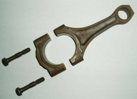
“A part of a machine or mechanism with relative motion with respect to any other.”
“Indivisible component of an element or mechanism.”
Kinematic pairs (Joints)#
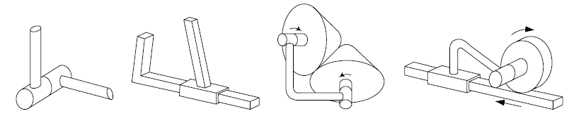
Between two contiguous bodies.
In permanent contact.
With relative motion between them. The degree of the joint is the number of degrees of freedom (d.o.f.) it allows.
Additional classification of Joints by Contact Type#
In addition to their degrees of freedom, kinematic pairs are also classified according to the nature of the contact between the links:
Lower pairs: Contact between the elements takes place over a surface. This allows loads to be distributed better and reduces wear. Typical examples are revolute
(R)and prismatic(P)joints.Higher pairs: Contact takes place along a line or at a point. They allow more complex motions, but concentrate stresses over a small area. Examples are the contact between two gear teeth or between a cam and its follower.
Kinematic chain#
Kinematic chain:
“Set of bodies put together with joints, such that they have relative motion.”
Mechanism:
“A kinematic chain with one fixed element (ground).”
Topological and abstract analysis of mechanisms#
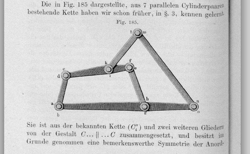
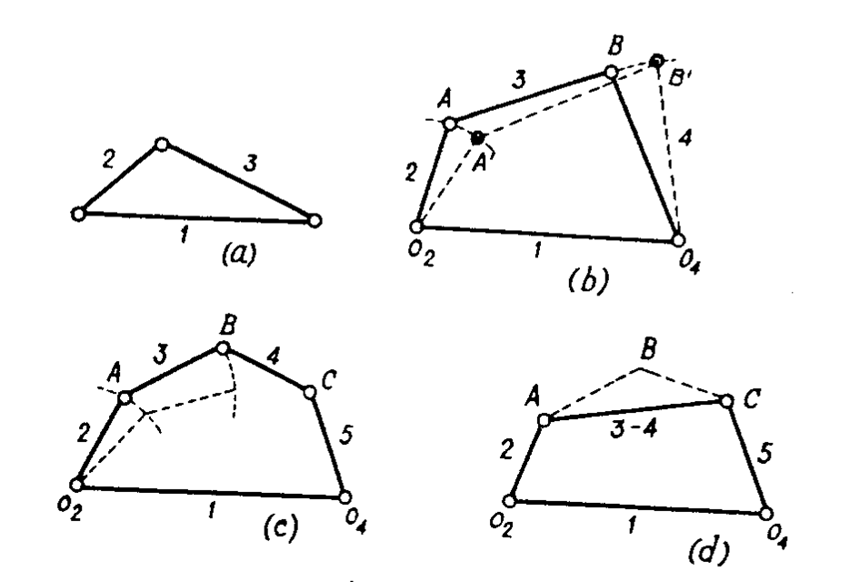
Franz Reuleaux proposed that it is enough to study the abstract kinematic chain of a mechanism to analyze its kinematic behavior. In his 1876 book, he invented an abstract notation to describe complex kinematic chains. The “graph” of a mechanism is a schematic representation of its links (edges) and joints (vertices) that captures its topology.
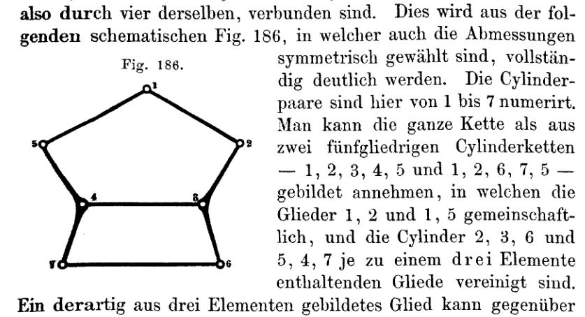
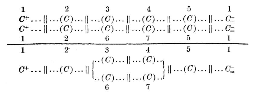
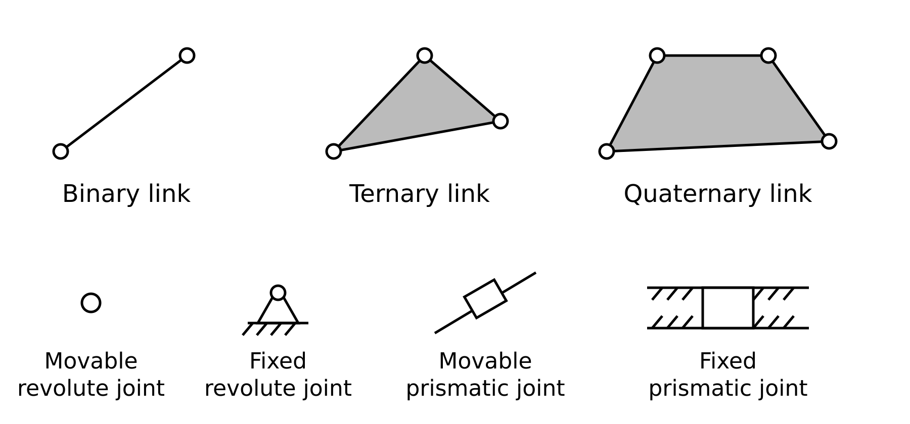
In some modern computer-based numerical methods, determining the graph corresponding to the mechanism chain remains a challenge. At a graphical level, a representation of this style is used:
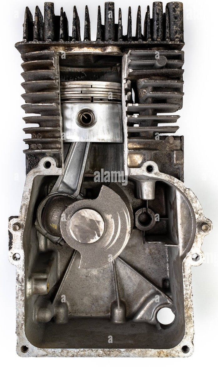
Example
Express the kinematic chain of the main mechanism of an internal combustion engine using Franz Reuleaux’s notation
Open and closed kinematic chains#
It depends on the existence of loops in the kinematic chain topology.
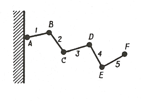
With these GeoGebra applets you can practice how an open-chain mechanism behaves versus a closed-chain one
Mobility and degrees of freedom#
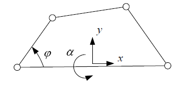
Mobility (\(M\)): number of parameters that must be specified to completely define its position.
Degrees of freedom (\(G\)): Idem. Due to the fixed element (ground), we have \(G = M - 3\) (for planar mechanisms).
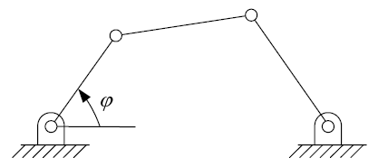
Five-bar mechanism:
In the following applet we can see a five-bar mechanism (or robot) as an example of a closed-chain mechanism with 2 degrees of freedom (d.o.f.)
Equivalent mechanisms#
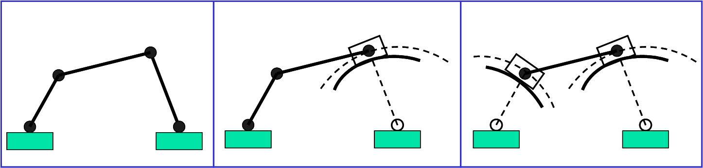
A mechanism, in a particular position, is kinematically equivalent to another one if it undergoes the same velocities and accelerations.
Kinematic inversion#
Swapping the role of two elements.
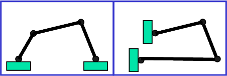
If we focus on the role of “ground” (fixed element), then there exist \(N-1\) inversions for a chain of N links.
Dyads#
In kinematics, an Assur group is a kinematic chain with zero degree of mobility that, when added to or removed from a mechanism, does not alter its original number of degrees of freedom. They were first described by the Russian engineer Leonid Assur (1878-1920) in 1914.
The simplest of all Assur groups (also known as dyads) has two links and three kinematic pairs, of which two are potential pairs (not yet active in the mechanism, but that could be activated if connected to other links). Using an underscore “_” to indicate a guide that follows or precedes a slider in a translational (prismatic) joint, the following figure shows the most commonly used dyads.
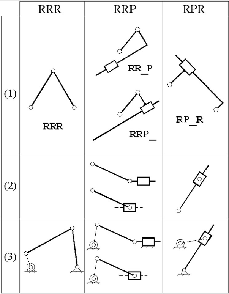
They can be of great interest when added to a rocker-rocker four-bar mechanism to achieve a mechanism with continuous rotation. In this case, they are called driving dyads and, as will be seen in the chapter on Introduction to Mechanism Synthesis, they are especially useful in function-generation synthesis problems.