Rotation and translation transformations#
Homogeneous transformation matrices#
The kinematic model of a robot is based on applying the existing transformations between the reference frames associated with each of the links that compose it. These reference systems will be translated and rotated from each other, depending on both the intrinsic geometric characteristics of the robot and the instructions adopted by its actuators. For this reason, it is crucial to know how these transformations are carried out. To do this, a mathematical tool called Homogeneous Transformation Matrix is used. This matrix allows knowing the position of a point belonging to a mobile reference system that has undergone a certain rotation and translation transformation with respect to a fixed system, as shown in the following Figure:
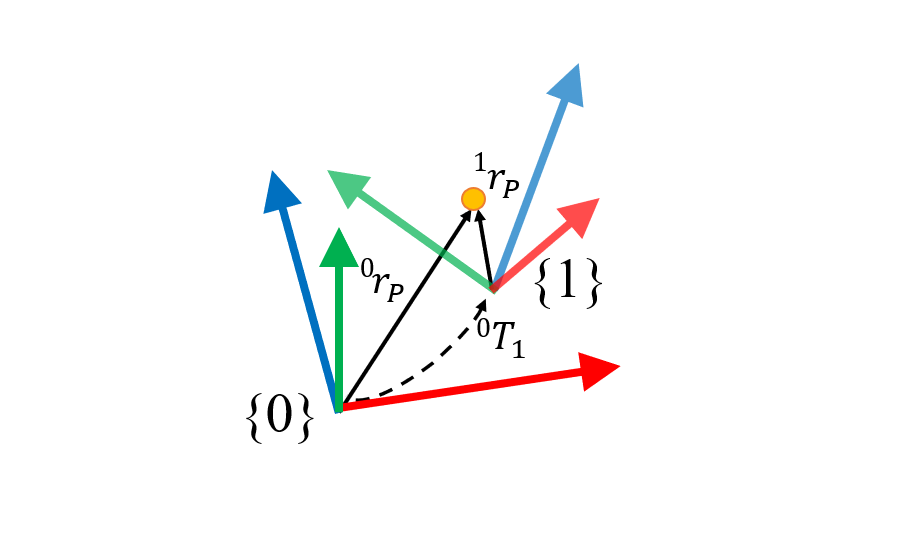
From which it follows that:
This is the way the homogeneous transformation matrix is generally expressed, especially in the field of robotics. However, in some problems it is necessary to know the coordinates of a point in the moving reference frame from the coordinates in the fixed frame. In these cases, the inverse of the homogeneous transformation matrix will be used (not the transposed one), as follows:
Obtaining the homogeneous transformation matrix#
Once we know what the homogeneous transformation matrix is and what it is used for, let’s see how we can obtain it. Although it is true that there are various methods, the most widespread is based on the combination of successive elementary rotations (with respect to the X, Y, Z axes) and Cartesian translations. These rotations and translations can be with respect to fixed axes or with respect to fixed axes. In turn, the translation can be carried out first followed by the rotation or vice versa. Obviously, the result of each of these possibilities is different, as shown in the following Figure:
The calculation procedure for each of the options is shown below:
In addition, the Denavit-Hartemberg sequence has also been implemented, which turns into the following transformation matrix:
The simulator#
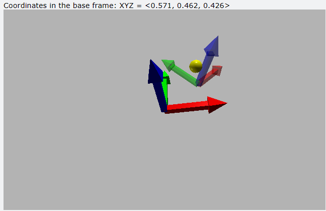
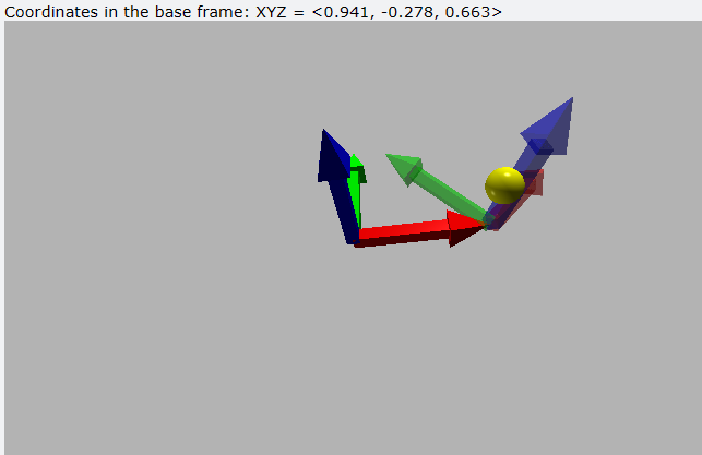
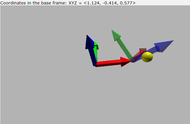
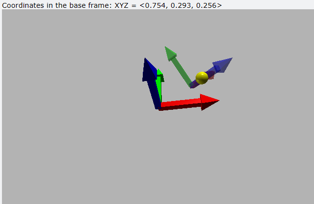
The previous expressions have been implemented in an interactive tool that carries out the associated calculations as well as the visual representation of the reference systems and the point involved. Its use is simple and consists of the following steps:
Run the simulator by clicking on the
RunbuttonChoose whether follower axes or
base axeswill be usedChoose whether the rotations will be carried out
firstand then the translations or vice versa.Select the
sequenceof axes in which the rotations will be carried out. Take into account that the D-H sequence only works with follower axes and thetranslation firstcheckbox deactivated.Act on the first three sliders if the ‘Carry out the translations first’ option was not chosen. If you activate the option to perform the translations first, start with sliders
4,5,6, then perform the rotations with sliders1,2,3.Finally, act on the sliders
7,8,9to define the location of point P with respect to the mobile system, and observe its position with respect to the fixed system in the image title. Right-click and rotate to change the point of view.
Conclusions#
A method has been presented to express the rotations and translations between two reference systems using the matrix known as the transformation matrix. Said matrix can be constructed from rotation sequences in fixed or follower axes accompanied by a priori or posterior translation. All these possibilities are included in the proposed interactive web-based tool [1]. This tool constitutes the basis on which the Denavit-Hartenberg method is based, through which the kinematic model of any serial robot is developed. The next chapter explains how this method is implemented. For more details about standard rotations visit this web where a conversion tool can be used.