The Interference Phenomenon#
The involute geometry works out mathematically perfectly, but it has physical limitations when built into a real gear. The involute is born at the base circle (\(d_b = d \cos \alpha\)). Below this circle, the involute curve does not exist mathematically.
During the cutting process (generation by rolling with a rack), if the number of teeth is too small, the rack tries to cut the profile below the base circle. Since the involute cannot extend there, the tip of the tool removes material from the tooth root that should remain.
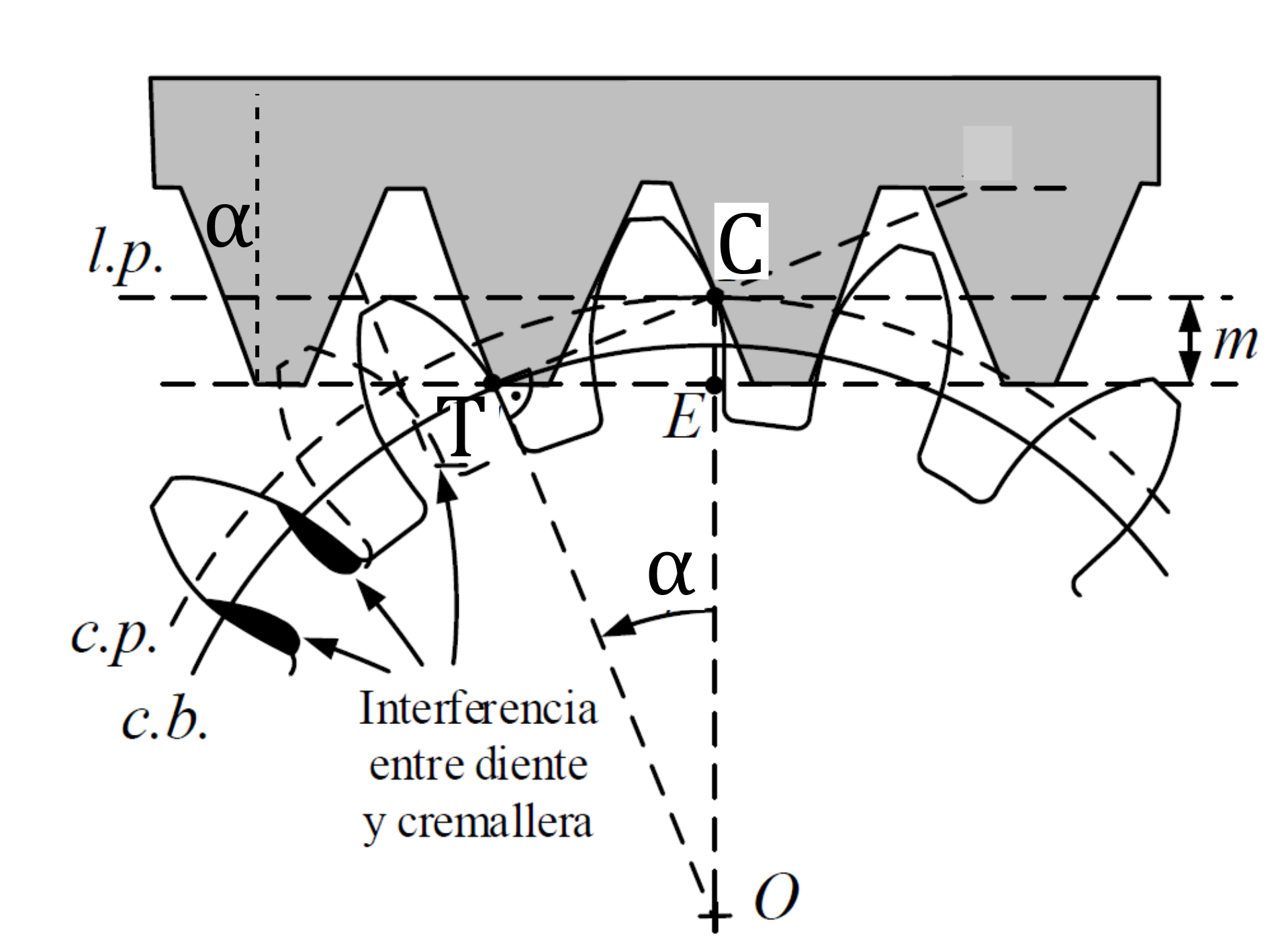
This defect is called cutting interference, or undercutting. Its consequences are:
Weakening: The tooth root becomes narrower, drastically reducing its bending strength.
Loss of contact: Part of the active profile near the root is removed, reducing the contact ratio (fewer teeth in simultaneous contact).
The theoretical tooth-number limit (\(Z_{lim}\))#
For a standard pressure angle of \(\alpha = 20^\circ\) and addendum height \(h_a = m\), the minimum number of teeth to mathematically avoid interference is:
\(Z_{lim} = \frac{2}{\sin^2(20^\circ)} \approx 17.09 \rightarrow \textbf{17 teeth}\)
Cases according to the number of teeth#
Depending on the number of teeth of the wheels we want to manufacture, we face three scenarios:
Safe zone (\(Z \ge 17\))#
If the pinion has 17 or more teeth, the geometry is perfect without needing any tricks.
The tooth is sturdy at the root.
Standard gears can be used with no correction (\(x=0\)).
Acceptable-risk zone (\(14 \le Z < 17\))#
Between 14 and 17 teeth, interference theoretically exists, but it is mild. In non-critical applications, this slight undercutting can be tolerated.
The practical criterion \(Z_{min\_practical} \approx 14\) is often used.
Critical interference zone (\(Z < 14\))#
Below 14 teeth, undercutting is severe. The tooth root becomes so weakened that the gear is unusable unless a correction is applied.
Tooth Correction (Profile Shift)#
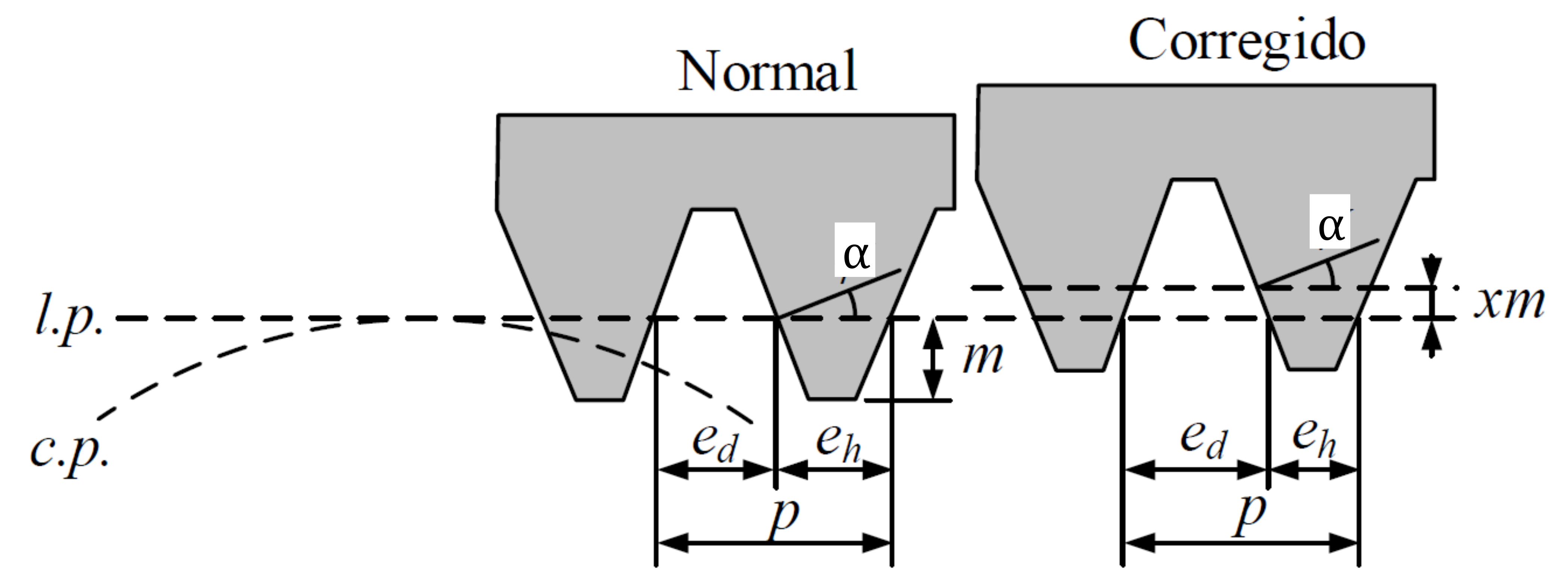
To avoid undercutting in small wheels (\(Z < 17\)), we use the profile-shift technique. It consists of moving the cutting tool (rack) an extra distance away from the center of the wheel during cutting.
This distance is defined as \(x \cdot m\), where \(x\) is the correction (profile-shift) coefficient.
Positive correction (\(x > 0\)): The tool moves away from the center.
The tooth becomes wider at the root (stronger).
The tooth becomes sharper at the tip.
Undercutting is eliminated.
Negative correction (\(x < 0\)): The tool moves closer to the center. Rarely used on pinions; more common on internal wheels or to adjust center distances.
Minimum correction value#
To completely avoid undercutting, the minimum required shift is:
\(x_{min} = \frac{17 - Z}{17}\)
However, a practical criterion (tolerable-undercutting criterion) allowing smaller corrections is often used instead:
\(x_{practical} = \frac{14 - Z}{17}\)
Mounting Types and Center Distance#
When corrections are introduced (\(x_1, x_2\)), the tooth thickness changes. This affects how two wheels can mesh with each other.
There are two broad families of mounting, depending on the sum of the corrections (\(\sum x = x_1 + x_2\)):
Zero (long-and-short-addendum) mounting (\(\sum x = 0\))#
Applied when one of the gears is small (\(Z_1 < 17\)) but the other is large, and the total number of teeth is generous (\(Z_1 + Z_2 \ge 34\)).
Strategy: We give the pinion a positive correction (\(x_1 > 0\)) to strengthen it, and remove that same amount from the wheel (\(x_2 = -x_1\)).
Consequence: The pinion teeth get thicker and the wheel’s teeth get thinner, but the total space is preserved.
Center distance (\(a\)): Stays at the standard value.
\(a = m \frac{Z_1 + Z_2}{2}\)
Pressure angle: Stays at \(20^\circ\).
V-mounting (\(\sum x \neq 0\))#
If both gears are small (\(Z_1 + Z_2 < 34\)), both need a positive correction (\(x_1 > 0, x_2 > 0\)).
Problem: Both sets of teeth are thicker than normal. If we tried to mount them at the standard distance, they would jam (there is no room).
Solution: The shafts must be separated by a larger distance.
Consequence: By separating the shafts, the operating pressure angle (\(\alpha'\)) increases.
Geometric Calculation of V-mounting#
To calculate the operating parameters (new angle and new distance) in a V-mounting, linear trigonometry cannot be used. The involute property must be used instead.
Fundamental equations#
Calculating the new pressure angle (\(\alpha'\)): The governing relation is the involute function (\(\text{inv}(\theta) = \tan\theta - \theta\)):
\(\text{inv}(\alpha') = \text{inv}(\alpha) + 2 \tan(\alpha) \frac{x_1 + x_2}{Z_1 + Z_2}\)
Note: This equation requires numerical iteration or tables to solve for \(\alpha'\).
Calculating the operating center distance (\(a'\)): Once \(\alpha'\) is obtained, the new distance is calculated by projecting the base radii:
\(a' = a_{std} \cdot \frac{\cos(\alpha)}{\cos(\alpha')}\)
Worked Examples#
Case A: Zero mounting (correction without change in center distance)#
Problem statement: Determine the dimensions of two gears mounted with no backlash, whose pinion has \(Z_1=10\) teeth and whose wheel has \(Z_2=35\) teeth. Module \(m=6\), angle \(\alpha=20^\circ\). We will use the practical correction criterion \(x = (14-Z)/17\).
1. Preliminary analysis:
\(Z_1 = 10 < 14\): The pinion has severe interference. It needs a positive correction.
\(Z_1 + Z_2 = 10 + 35 = 45 \ge 34\): The total number of teeth is high. A zero mounting is possible.
2. Determining the corrections (\(x_1, x_2\)): We calculate the correction required for the pinion:
\(x_1 = \frac{14 - 10}{17} = \frac{4}{17} \approx \mathbf{0.2353}\)
To keep the standard center distance (zero mounting), we require the wheel’s correction to exactly compensate the pinion’s:
\(x_2 = -x_1 = \mathbf{-0.2353}\)
Safety check for the wheel: we must verify that this negative correction does not cause interference in the wheel (\(Z_2=35\)).
\(x_{2,limit} = \frac{14 - 35}{17} \approx -1.23\)
Since our applied correction (\(-0.235\)) is much smaller than the limit (\(-1.23\)), it is completely safe.
3. Calculating the geometric parameters: Since this is a zero mounting (\(\sum x = 0\)), the pressure angle and the center distance do not change.
Center distance (\(a\)):
\(a = m \frac{Z_1+Z_2}{2} = 6 \frac{45}{2} = \mathbf{135 \text{ mm}}\)
Addendum (tip) radii: The correction affects the outside diameter. The formula is \(r_a = r + m(1+x)\).
Pinion: \(r_1 = m Z_1 / 2 = 30\) mm.
\(r_{a1} = 30 + 6(1 + 0.2353) = 30 + 7.41 = \mathbf{37.41 \text{ mm}}\)
Wheel: \(r_2 = m Z_2 / 2 = 105\) mm.
\(r_{a2} = 105 + 6(1 - 0.2353) = 105 + 4.59 = \mathbf{109.59 \text{ mm}}\)
Case A (variant): V-mounting (asymmetric correction)#
Problem statement: In the previous example, what parameters would the gears have, and what would the shaft distance be, if we want to keep zero circumferential backlash, but the \(Z_2=35\)-tooth wheel is cut with no profile shift?
1. Correction analysis:
Pinion (\(Z_1=10\)): We keep the correction needed to avoid interference, \(x_1 = (14-10)/17 \approx 0.2353\).
Wheel (\(Z_2=35\)): The problem statement imposes \(x_2 = 0\).
Sum of corrections: \(\sum x = 0.2353 + 0 = 0.2353\). Since \(\sum x > 0\), this is a V-mounting.
2. Calculating the operating pressure angle (\(\alpha'\)): Applying the involute formula:
\(\text{inv}(\alpha') = \text{inv}(20^\circ) + 2 \tan(20^\circ) \frac{0.2353}{10 + 35}\)
The numerical result gives: \(\alpha' \approx \mathbf{21.52^\circ}\)
3. Calculating the center distance (\(a'\)): The standard distance is \(a = 135.000\) mm. The new operating distance will be:
\(a' = 135 \cdot \frac{\cos(20^\circ)}{\cos(21.52^\circ)} \approx \mathbf{136.36 \text{ mm}}\)
Conclusion: By not compensating the pinion’s correction on the wheel (leaving \(x_2=0\)), the teeth “take up more space” than standard, forcing the shafts to be separated by an additional 1.36 mm relative to the theoretical position.
Case B: V-mounting (correction with change in center distance)#
Problem statement: Calculate the operating parameters of a pair of gears with \(m=8\), pinion \(Z_1=8\), wheel \(Z_2=11\), angle \(\alpha=20^\circ\). Mounted with no backlash.
1. Preliminary analysis:
Both have \(Z < 14\): critical interference in both.
\(Z_1 + Z_2 = 19 < 34\): a V-mounting is mandatory (both need \(x > 0\)).
2. Determining the corrections:
\(x_1 = \frac{14 - 8}{17} \approx 0.3529\)
\(x_2 = \frac{14 - 11}{17} \approx 0.1765\)
Sum of corrections: \(\sum x = 0.5294\).
3. Calculating the operating pressure angle (\(\alpha'\)):
\(\text{inv}(\alpha') = \text{inv}(20^\circ) + 2 \tan(20^\circ) \frac{0.5294}{19}\)
\(\text{inv}(\alpha') = 0.014904 + 0.02028 = \mathbf{0.035187}\)
\(\rightarrow \alpha' \approx \mathbf{26.31^\circ}\)
4. Calculating the center distance (\(a'\)): Standard distance (\(a\)): \(76 \text{ mm}\).
\(a' = 76 \cdot \frac{\cos(20^\circ)}{\cos(26.31^\circ)} = \mathbf{79.67 \text{ mm}}\)
Comparison summary (Case B)#
Parameter |
Standard (theoretical) value |
Real value (V-mounting) |
|---|---|---|
Pressure angle |
\(\alpha = 20^\circ\) |
\(\alpha' = 26.31^\circ\) |
Center distance |
\(a = 76 \text{ mm}\) |
\(a' = 79.67 \text{ mm}\) |
Pitch diameter 1 |
\(d_1 = 64 \text{ mm}\) |
\(d'_1 = 67.09 \text{ mm}\) |
Pitch diameter 2 |
\(d_2 = 88 \text{ mm}\) |
\(d'_2 = 92.25 \text{ mm}\) |
Appendix: Involute Function Table#
Values of the function \(\text{inv}(\alpha) = \tan(\alpha) - \alpha\) (with \(\alpha\) in radians) for typical angles.
\(\alpha\) (degrees) |
\(\text{inv}(\alpha)\) |
\(\alpha\) (degrees) |
\(\text{inv}(\alpha)\) |
|---|---|---|---|
10.0 |
0.00179 |
20.5 |
0.01609 |
10.5 |
0.00208 |
21.0 |
0.01734 |
11.0 |
0.00239 |
21.5 |
0.01866 |
11.5 |
0.00274 |
22.0 |
0.02005 |
12.0 |
0.00312 |
22.5 |
0.02151 |
12.5 |
0.00353 |
23.0 |
0.02305 |
13.0 |
0.00398 |
23.5 |
0.02466 |
13.5 |
0.00446 |
24.0 |
0.02635 |
14.0 |
0.00498 |
24.5 |
0.02812 |
14.5 |
0.00554 |
25.0 |
0.02998 |
15.0 |
0.00615 |
25.5 |
0.03192 |
15.5 |
0.00680 |
26.0 |
0.03395 |
16.0 |
0.00749 |
26.5 |
0.03607 |
16.5 |
0.00823 |
27.0 |
0.03829 |
17.0 |
0.00902 |
27.5 |
0.04060 |
17.5 |
0.00987 |
28.0 |
0.04302 |
18.0 |
0.01076 |
28.5 |
0.04554 |
18.5 |
0.01171 |
29.0 |
0.04816 |
19.0 |
0.01272 |
29.5 |
0.05090 |
19.5 |
0.01378 |
30.0 |
0.05375 |
20.0 |
0.01490 |
30.5 |
0.05672 |