Introduction and Prerequisite Concepts#
A gear train is a kinematic chain formed by several toothed wheels (gears) that mesh with one another. Gear trains are used whenever transmitting power or motion with a single pair of gears is not feasible.
When should a gear train be used?#
There are physical and design limitations that prevent using just two gears for every application:
Very high gear ratio (\(i\)): Achieving it with a single pair would require an enormous wheel and a tiny pinion, which is inefficient and bulky.
Irreducible ratio \(i\): If the terms of the desired fraction contain prime factors too large to fit within the maximum admissible number of teeth (e.g. 127, 131…), they cannot be manufactured directly.
Irrational ratio \(i\): Incommensurable values such as \(\pi\) or \(\sqrt{7}\) cannot be obtained exactly with integer numbers of teeth, and require approximations (see Section 7).
Large center distance: This would require excessively large-diameter gears, increasing weight and inertia.
Need to reverse the direction of rotation or to split the motion across several shafts (as in differentials).
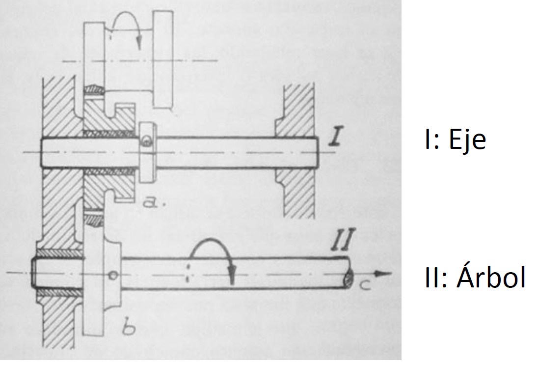
A fundamental distinction: Axle vs. Shaft#
It is essential to distinguish these two mechanical elements, even though they are colloquially used as synonyms:
Axle: An element that supports rotating parts but does NOT transmit torque. Its main stress is bending. It may be fixed or rotating.
Shaft: A rotating element that does transmit power (torque) and motion. It is subjected to torsion and bending.
Design note: In gear trains, torque is computed on the transmission shafts.
Design Criteria#
To guarantee optimal, manufacturable operation, gear train design should follow a set of practical recommendations that ensure the mechanical and economic feasibility of the assembly.
Choosing the Number of Teeth (\(Z\))#
Lower bound (interference): The practical limit of 14 teeth must be respected.
If \(Z \ge 14\): safe, standard design.
If \(Z < 14\): profile correction (shift) must be specified to avoid undercutting and weakening of the tooth.
Upper bound: The maximum wheel size is limited by the capacity of the gear-cutting machine and the available space.
General industrial applications: up to 100-150 teeth.
Precision mechanics (watchmaking): up to 200 teeth are admissible.
Gear Ratio per Stage#
It is not advisable to perform the whole reduction in a single stage if the required ratio is very high.
Maximum thresholds: The partial gear ratio of each meshing pair is recommended not to exceed values between 5 and 10 (5-7 being the usual limit for power transmission).
Rationale: Higher ratios imply very small pinions against very large wheels, which reduces the contact arc, lowers efficiency, and increases noise and wear.
Distributing the ratio: In compound trains, the partial ratios of the different gear groups should be made as similar as possible to each other.
Optimization Strategies#
Standardization: Whenever possible, as many gears as possible should share the same number of teeth, to reduce manufacturing and stock costs.
Selection criterion: Given two kinematically equivalent designs, the one with the lowest total number of teeth is usually preferred (less weight, inertia, and cost).
Estimating the number of stages: If a total ratio \(i_{total}\) is required and a per-stage limit \(i_{max}\) is set, the minimum number of stages (\(x\)) needed is estimated as: \(x \ge \frac{\log(i_{total})}{\log(i_{max})}\) The number of shafts involved will be \(x + 1\).
Shaft Arrangement#
Recurrent (coaxial) trains: Trains where the input and output shafts are geometrically aligned. Typical of automotive gearboxes and planetary reducers.
Sign of the transmission: The final direction of rotation depends on the product of the signs of each stage.
Classification of Gear Trains#
Depending on the mobility of the gear axes, trains are classified as:
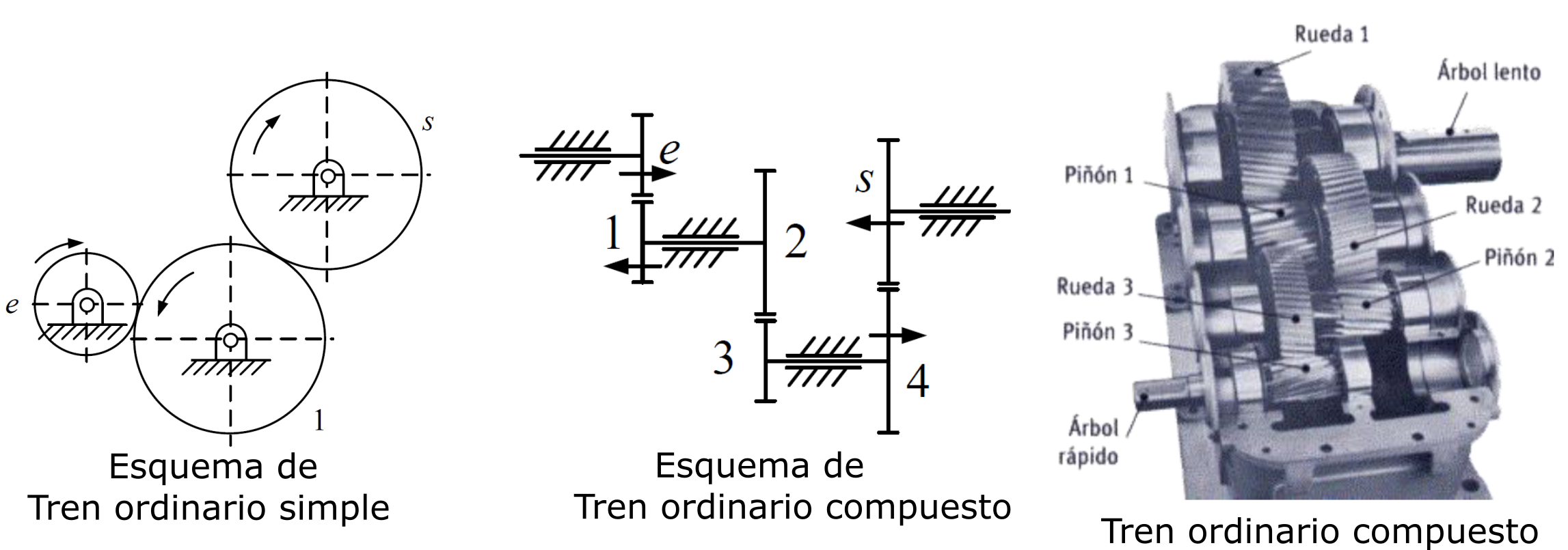
Ordinary gear trains: All rotation axes are fixed in space (supported on the housing or frame).
Epicyclic (or planetary) gear trains: At least one of the gear axes has a rotational motion about another axis. These are systems with 2 degrees of freedom.
Ordinary Gear Trains#
In these trains, the total gear ratio is computed from the ratios of each meshing pair.
4.1. Simple Ordinary Gear Train#
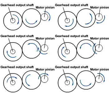
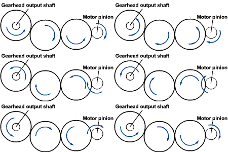
There is a single gear on each shaft.
Intermediate gears (called “idler gears”) reverse the direction of rotation but do not affect the numerical value of the final gear ratio. Only the size of the first and last gear matter.
\(i = \frac{\omega_{output}}{\omega_{input}} = (-1)^n \cdot \frac{Z_{input}}{Z_{output}}\)
(Where \(n\) is the number of external meshes.)
4.2. Compound Ordinary Gear Train#
Some shafts carry more than one gear (gears rigidly attached to the same shaft). Here, the intermediate gears do affect the gear ratio.
General formula: The total gear ratio is the product of the partial ratios:
\(i_{total} = \frac{\omega_{output}}{\omega_{input}} = (\pm 1) \cdot \frac{\Pi Z_{driving}}{\Pi Z_{driven}}\)
Sign: Depends on the number of external meshes (each one reverses the direction of rotation).
Advantage: Allows obtaining large reductions in a small space.
Synthesis of Gear Trains#
The inverse problem: given a desired ratio \(i\), how many teeth should the gears have?
Case 1: \(i\) is a factorizable rational number#
If \(i = A/B\) and it can be decomposed into prime factors suitable for gear cutting (\(Z \ge 17\), or \(Z \ge 14\) with a small correction).
Case 2: \(i\) is irrational or has large prime factors#
When an exact, feasible fraction cannot be found.
Reminder from Lesson 7: This procedure was detailed in the previous lesson (“Velocity Ratio and Number of Teeth: the Continued-Fraction Method”).
Continued fraction method: The target number is expanded as a continued fraction and truncated to obtain rational convergents that minimize the error while using manufacturable numbers of teeth.
\(i \approx a_0 + \frac{1}{a_1 + \frac{1}{a_2 + \dots}}\)