
Example 3.1: Robotic gripper (quasi-static analysis)#
The figure shows the mechanism of a robotic gripper, with dimensions in cm. A gripping force \(F_g = 25\) N is required at each finger. Neglecting gravity, what must the actuator force \(F_a\) be? To design the support structure of the gripper, compute also the reaction at the pin \(O_2\).
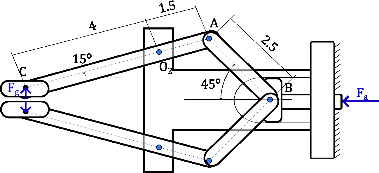
The upper finger (link 2) pivots about \(O_2\) and is at \(15^\circ\) from the horizontal; bar \(AB\) (link 3) is at \(45^\circ\); the actuator moves block \(B\) (link 4) horizontally. The mechanism moves slowly, so the analysis is quasi-static: inertia loads are negligible.
Graphical solution (equilibrium of each link)
By symmetry, it is enough to study the upper finger. Bar \(AB\) carries no loads and has no mass: it is a two-force member, and the force \(F_{AB}\) it transmits acts along the bar, at \(45^\circ\).
Link 2. Taking moments about \(O_2\) (counterclockwise positive), the reaction at \(O_2\) does not appear:
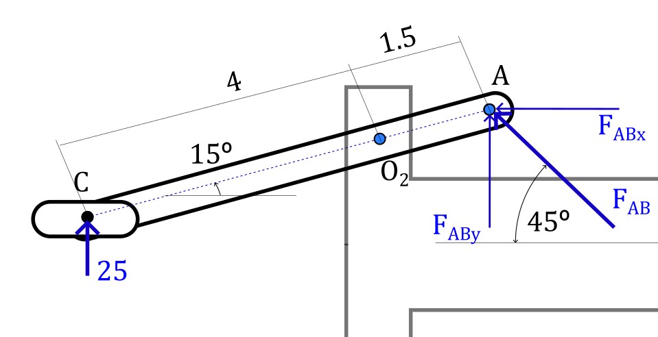
which gives \(F_{AB} = 74.4\) N.
Link 4. Block \(B\) receives the forces of both bars (the one of the upper finger and the one of the lower finger, symmetric) and the actuator force:
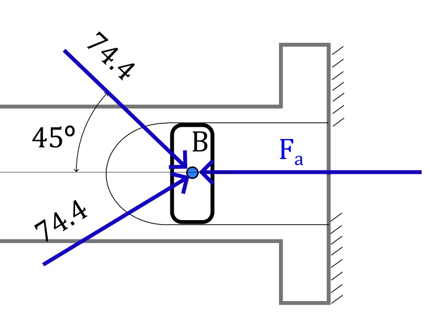
The vertical components cancel out by symmetry, and the horizontal ones add up:
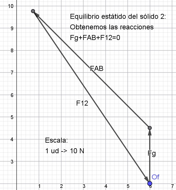
Reaction at \(O_2\). It is obtained by closing the force polygon of link 2, \(\vec{F}_g + \vec{F}_{AB} + \vec{F}_{12} = \vec{0}\):
Analytical solution (system of equations)
The systematic procedure is to write the force and moment equilibrium equations of all bodies and solve them simultaneously. We keep studying the upper half; its share of the actuator force is \(F_a/2\).
Position vectors (in cm), with \(\hat{i}\) to the right and \(\hat{j}\) upwards:
Body 2. From the free-body diagram:
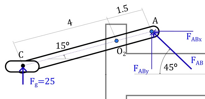
with \(\vec{F}_g = 25\,\hat{j}\) N. All unknown components are written as positive; the sign of the result gives their sense.
Body 3.
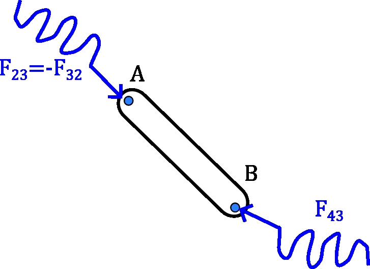
We use \(\vec{F}_{23} = -\vec{F}_{32}\) to avoid duplicating unknowns.
Body 4 (half of the block, actuator force \(-F\,\hat{i}\), horizontal guide):
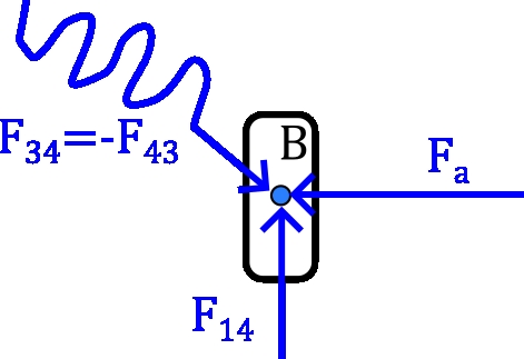
Solution. These are 8 scalar equations with 8 unknowns (\(F_{12x}\), \(F_{12y}\), \(F_{32x}\), \(F_{32y}\), \(F_{43x}\), \(F_{43y}\), \(F_{14y}\), \(F\)). In MATLAB:
syms F12x F12y F32x F32y F43x F43y F14y F real
rO2A = 1.5*[cosd(15) sind(15) 0];
rO2C = -4*[cosd(15) sind(15) 0];
rAB  = 2.5*[cosd(45) -sind(45) 0];
Fg = [0 25 0];
F12 = [F12x F12y 0]; F32 = [F32x F32y 0]; F43 = [F43x F43y 0];
eq1_2 = F32 + F12 + Fg == 0;
eq3   = cross(rO2A, F32) + cross(rO2C, Fg) == 0;
eq4_5 = F43 - F32 == 0;
eq6   = cross(rAB, F43) == 0;
eq7_8 = [0 F14y 0] - F43 - [F 0 0] == 0;
sol = solve([eq1_2(1:2), eq3(3), eq4_5(1:2), eq6(3), eq7_8(1:2)], ...
    [F12x, F12y, F32x, F32y, F43x, F43y, F14y, F]);
structfun(@double, sol)
Result: \(\vec{F}_{32} = \vec{F}_{43} = -52.58\,\hat{i} + 52.58\,\hat{j}\) N (the bar is in compression with \(74.4\) N), \(\vec{F}_{12} = 52.58\,\hat{i} - 77.58\,\hat{j}\) N, \(F = 52.58\) N, and therefore \(F_a = 2F = 105.15\) N, as in the graphical solution. The reaction \(F_{14y} = 52.58\) N of the upper half cancels out with that of the lower half, so the actuator guide carries no load.