Example 3.4: Slider-crank with the mass at the slider#
In the slider-crank mechanism of the figure, crank \(OA\) (of length \(L\)) rotates with constant angular velocity \(\omega\) counterclockwise, driven by an unknown input torque \(\tau\). The connecting rod \(AB\) is \(2L\) long. Knowing that the crank and the rod have negligible mass and that the mass of the slider is \(M\), compute the instantaneous torque \(\tau\) when the crank is at \(45^\circ\) from the horizontal. Neglect weight and friction.
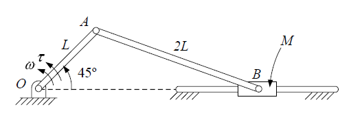
(Example solved in [AI14].) We follow the three steps of D’Alembert’s principle: kinematics, inertia loads and static equilibrium.
Step 1: kinematics
Position. With \(O\) at the origin and \(\theta = 45^\circ\):
The slider is level with \(O\): \(x_B = L\cos 45^\circ + \sqrt{(2L)^2 - (L \sin 45^\circ)^2} = 2.5779\,L\), and therefore:
with \(\beta\) the angle between the rod and the horizontal (below it).
Velocities. \(\vec{v}_A = \vec{\omega}\times\vec{r}_{OA} = \omega L\,(-0.7071, 0.7071)\), and \(\vec{v}_B = v_B\,\hat{i} = \vec{v}_A + \vec{\omega}_3 \times \vec{r}_{AB}\). Equating components:
Accelerations. With constant \(\omega\), \(\vec{a}_A = -\omega^2\vec{r}_{OA} = \omega^2 L\,(-0.7071, -0.7071)\), and:
The slider moves to the left (\(v_B < 0\)) faster and faster (\(a_B < 0\), same sign).
Step 2: inertia loads
Only the slider has mass, and it translates: it has an inertia force, but no inertia torque. The inertia force is opposite to its acceleration:
applied at \(B\).
Step 3: equilibrium (analytical solution)
Rod (link 3). It has no mass and no loads: it is a two-force member and transmits a force along \(AB\). Let \(\vec{u} = \vec{r}_{AB}/|\vec{r}_{AB}| = (\cos\beta, -\sin\beta)\) and \(\vec{F}_{34} = F_{34}\,\vec{u}\) be the force of the rod on the slider (\(F_{34} > 0\) if it pushes, compression).
Slider (link 4). It receives \(\vec{J}_4\), \(\vec{F}_{34}\) and the guide reaction \(\vec{F}_{14} = N\,\hat{j}\):
The negative sign of \(F_{34}\) means that the rod pulls the slider (tension), and that of \(N\), that the guide pushes downwards.
Crank (link 2). The rod exerts \(\vec{F}_{32} = -\vec{F}_{34}\) on it at \(A\). Taking moments about \(O\):
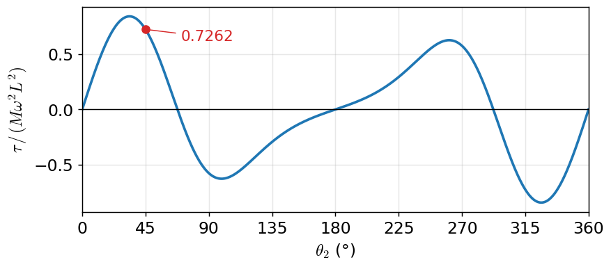
Power check. The power of the input torque plus that of the inertia force is zero: \(\tau\,\omega + \vec{J}_4\cdot\vec{v}_B = 0\), so \(\tau = -J_4\, v_B / \omega = 0.7453 \cdot 0.9744\, M\omega^2L^2 = 0.7262\, M\omega^2L^2\). ✓
Step 3: equilibrium (graphical solution)
With the rod as a two-force member, the slider is a three-force member: \(\vec{J}_4\) (known), \(\vec{F}_{34}\) (along \(AB\)) and \(\vec{F}_{14}\) (perpendicular to the guide). All three go through \(B\), so closing the force triangle is enough to get the magnitudes and senses of \(\vec{F}_{34}\) and \(\vec{F}_{14}\). Then the force that the rod transmits to the crank has an arm \(d\) about \(O\), measured on the drawing (\(d = 0.9114\,L\)), and \(\tau = |\vec{F}_{32}|\, d = 0.7967 \cdot 0.9114\, M\omega^2L^2 = 0.7262\, M\omega^2L^2\).
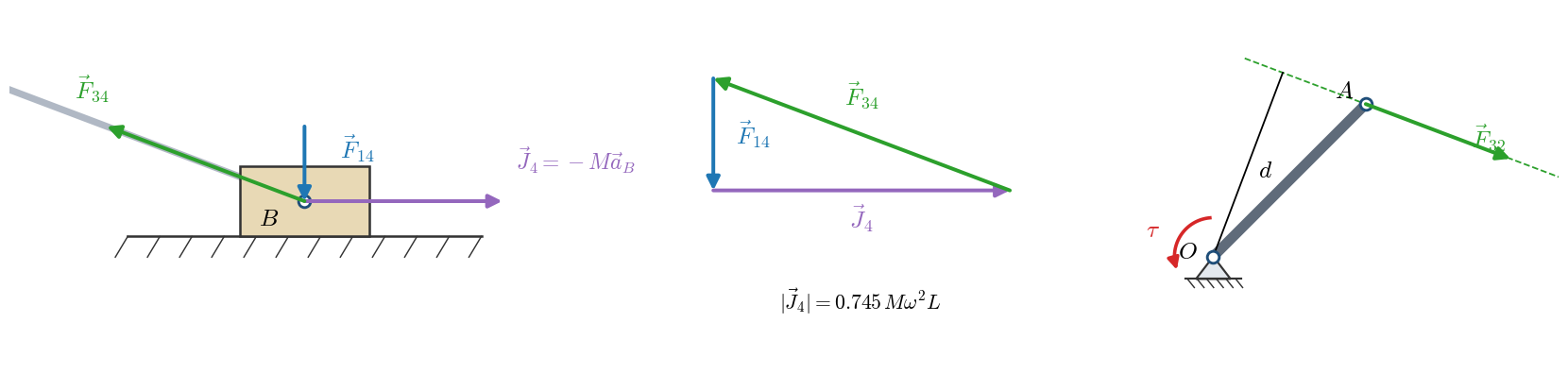
Interactive construction#
Go through the construction step by step. Dragging the crank shows the solution at any other position (magnitudes are given in units of \(M\omega^2L\) and \(M\omega^2L^2\)):
Torque over a revolution#
Repeating the computation at every position gives the curve of the torque needed to keep \(\omega\) constant. The torque changes sign: in some regions the motor has to accelerate the slider, and in others it must brake it. Its mean value over a revolution is zero, because the kinetic energy of the mechanism is the same at the beginning and at the end of the revolution (lesson 4). This fluctuating torque is what a flywheel smooths out.