
Instantaneous Centers of Rotation#
The instantaneous center of rotation (ICR, also called instant center) method is a graphical method to obtain velocities, alternative to the velocity polygon of Velocity Analysis. It is especially useful to find the velocity of one particular point, or the relation between the angular velocities of two links, without solving the whole mechanism.
Definition#
At any instant, a link in planar motion that is not translating has a point with zero velocity: the link is rotating about that point at that instant. To find it, start from the velocity of any point \(A\) of the link and look for a point \(I\) such that \(\vec{v}_I = \vec{v}_A + \vec{\omega} \times \vec{r}_{AI} = \vec{0}\). Multiplying both sides by \(\hat{k} \times\) and using \(\hat{k} \times (\hat{k} \times \vec{r}) = -\vec{r}\) for vectors on the plane:
That is, \(I\) lies on the line through \(A\) perpendicular to \(\vec{v}_A\), at a distance \(|\vec{v}_A|/|\omega|\) from \(A\). If \(\omega = 0\) (pure translation), it is at infinity. Since \(\vec{v}_I = \vec{0}\), the velocity of any other point \(P\) of the link is just:
as if the link were pinned at \(I\). This has three practical consequences:
The velocity of every point of the link is perpendicular to the line that joins it to the ICR, and its magnitude is proportional to its distance to the ICR.
If the directions of the velocities of two points of a link are known, its ICR is at the intersection of the lines perpendicular to them through each point.
Once the ICR is located, the velocity of a single point gives the angular velocity of the link, and with it the velocity of any other point.
The following animation shows these ideas on a triangular body:
More generally, for any two links \(j\) and \(k\), their instantaneous center \(I_{jk}\) is the point (of both links, or of their imaginary extensions) that has the same velocity in both links at that instant. Seen from link \(j\), link \(k\) is rotating about \(I_{jk}\). Centers where one of the links is the ground (\(I_{1k}\)) are called absolute, and the rest are relative centers.
Warning
The ICR is a point of zero velocity, but not of zero acceleration: its position changes from one instant to the next. Therefore, it cannot be used to compute accelerations as if the link were rotating about a fixed pivot.
Number of instantaneous centers#
There is one instantaneous center for each pair of links, including the ground. A mechanism with \(N\) links has:
For example, a four-bar linkage has \(4 \cdot 3 / 2 = 6\) centers: \(I_{12}, I_{13}, I_{14}, I_{23}, I_{24}\) and \(I_{34}\). It is advisable to write them all in a table, and cross them out as they are found.
Primary centers#
Some centers can be located directly by inspection of the joints:
Pin joint: the center of the pin is a point of both links with the same velocity, so it is their center \(I_{jk}\).
Slider on a straight guide: all the points of the slider move parallel to the guide relative to the other link, so their center is at infinity, in the direction perpendicular to the guide. Any line perpendicular to the guide “passes” through it.
Slider on a curved guide: at the center of curvature of the guide.
Rolling without slipping: at the contact point, where both bodies have the same velocity.
Contact with sliding (cams, gear teeth): somewhere on the common normal to both surfaces at the contact point. This gives a line, not a point: the exact location needs a second line, from Kennedy’s theorem.
Kennedy’s theorem#
The rest of the centers are found with the Aronhold-Kennedy theorem (or three centers theorem):
The three instantaneous centers of any three bodies in planar motion lie on a straight line.
Proof. Take the bodies 1, 2 and 3, with 1 as the reference (fixed), and assume \(I_{12}\) and \(I_{13}\) are known. Their common center \(I_{23}\) has the same velocity as a point of body 2, which rotates about \(I_{12}\), and as a point of body 3, which rotates about \(I_{13}\). As a point of body 2, its velocity is perpendicular to the line \(I_{12}I_{23}\); as a point of body 3, it is perpendicular to \(I_{13}I_{23}\). Both velocities can only be the same vector if both directions coincide, so \(I_{12}\), \(I_{13}\) and \(I_{23}\) must be aligned. On that line, \(I_{23}\) is the point where the magnitudes also coincide: \(\omega_2\,\overline{I_{12}I_{23}} = \omega_3\,\overline{I_{13}I_{23}}\).
To locate an unknown center \(I_{jk}\), apply the theorem twice, with two different third bodies \(m\) and \(n\) for which the other centers are known: \(I_{jk}\) lies on the line \(I_{jm}I_{mk}\) and also on the line \(I_{jn}I_{nk}\), so it is at their intersection.
A simple way to choose the lines is an auxiliary polygon, with one vertex per link and one side (or diagonal) per known center. An unknown center is a diagonal that closes two triangles whose other sides are already known; each triangle gives one line. The new center then becomes a known side, and the process is repeated until the table is complete:
The figure below shows the procedure for a four-bar linkage: a) the four primary centers, b) \(I_{13}\) from triangles 1-2-3 and 1-4-3, and c) \(I_{24}\) from triangles 2-1-4 and 2-3-4.
Example 1, below, repeats the procedure step by step as an interactive construction.
Velocity analysis with instantaneous centers#
Using an absolute center#
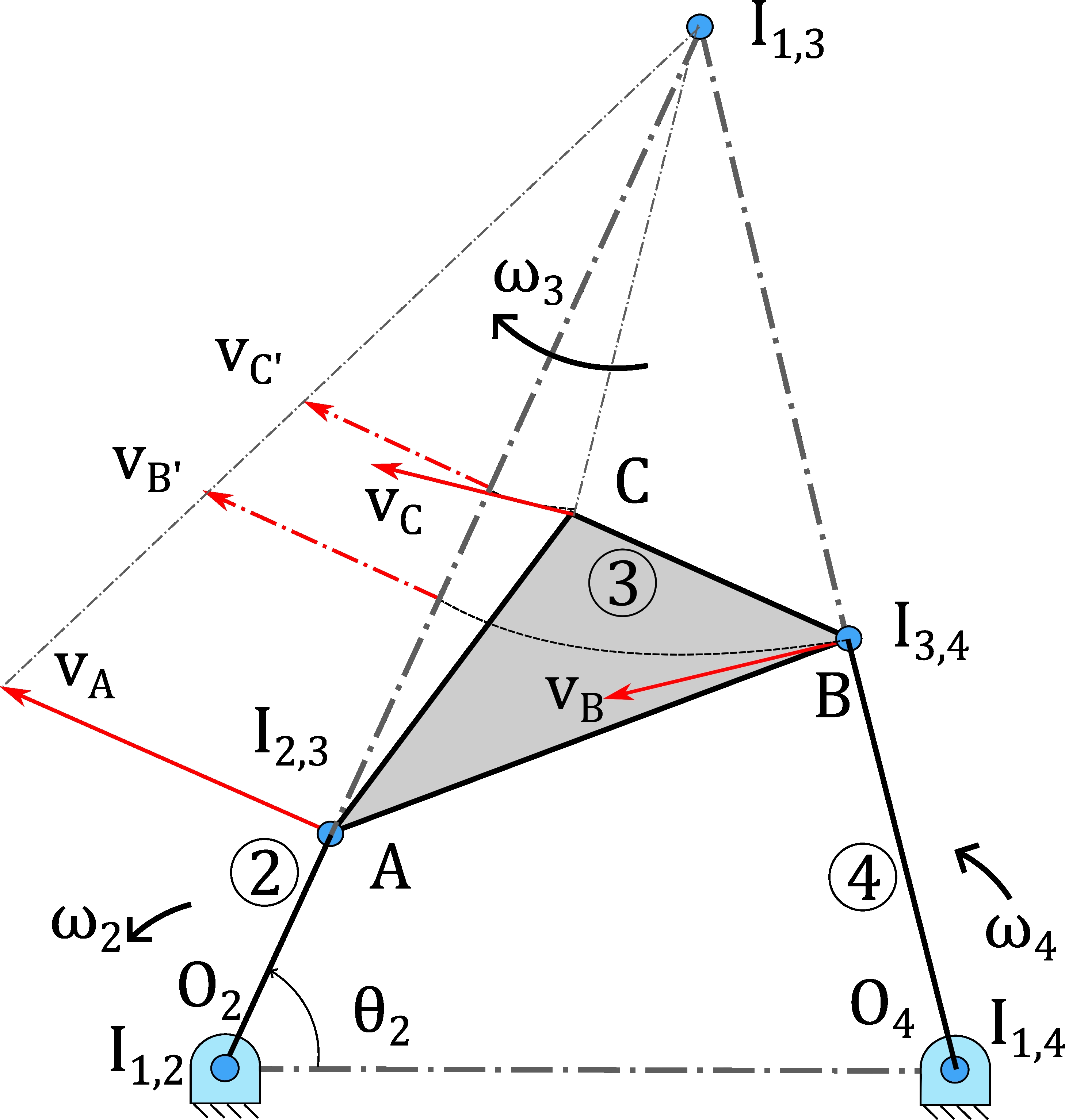
If the velocity of one point of a link is known, its absolute center gives the angular velocity of the link and the velocity of any other point. In the four-bar linkage of the figure below, \(\vec{v}_A\) is known from the crank, and link 3 rotates about \(I_{13}\), so:
with each velocity perpendicular to the line from \(I_{13}\) to its point. Graphically, the velocities of the points of link 3 are proportional to their distances to \(I_{13}\), so they can be transferred by drawing arcs centered at \(I_{13}\) (points \(B'\) and \(C'\) in the figure) onto the line \(I_{13}A\), where the proportionality is just a triangle.
Using a relative center: angular velocity ratio#
The relative center \(I_{24}\) of two links is a point that has the same velocity as a point of link 2 (rotating about \(I_{12}\)) and as a point of link 4 (rotating about \(I_{14}\)):
since the three centers \(I_{12}\), \(I_{14}\) and \(I_{24}\) are aligned (Kennedy). This angular velocity ratio theorem relates the input and output links directly, without computing anything on the coupler. Regarding the senses of rotation:
If \(I_{24}\) lies outside the segment \(I_{12}I_{14}\), both links rotate in the same sense.
If it lies between \(I_{12}\) and \(I_{14}\), they rotate in opposite senses.
The same reasoning applies to any pair of links. For a slider, which translates, the relative center with the input link is a point of the input link that moves exactly as the slider, so it gives the output velocity directly. This is shown in the following construction for a slider-crank, where the center of the slider with the ground, \(I_{14}\), is at infinity:
Step-by-step examples#
Example 1: four-bar linkage#
Find all the instantaneous centers of the four-bar linkage in the figure and, from them, the velocities. Data: \(O_2 = (0, 0)\), \(O_4 = (4, 0)\), \(\overline{O_2A} = 1.2\), \(\overline{AB} = 3.5\), \(\overline{O_4B} = 3\); point \(C\) of the coupler is at a distance \(2\) from \(A\), at \(30^\circ\) from \(AB\); \(\omega_2 = 1\) rad/s counterclockwise. Move the crank to see how the centers change with the position of the mechanism; note that \(I_{13}\) goes to infinity when links 2 and 4 are parallel, and that the numerical values are recomputed at each position.
Example 2: slider on a moving bar#
Quick-return mechanism: crank 2 drives slider 3 (pinned at \(A\)), which slides along bar 4, which rotates about \(O_4\). Data: \(O_2 = (0, 0)\), \(O_4 = (0, -3)\), \(\overline{O_2A} = 1.8\), bar length \(6.4\); \(\omega_2 = 1\) rad/s counterclockwise. One of the centers is at infinity, and the straight-slider rule is all that is needed: any line perpendicular to bar 4 “passes” through it.
Examples Example 2.14: Instantaneous centers of a four-bar linkage and Example 2.15: Bicycle suspension (graphical method) apply the method to two exam problems.
Summary#
The ICR of a body is its point of zero velocity: the whole body rotates about it at that instant.
There are \(N(N-1)/2\) ICRs. Primary centers are found at the joints; a straight slider has its center at infinity.
Kennedy’s theorem: the ICRs of any three bodies are aligned. Two lines give one ICR.
Auxiliary polygon: each new ICR is a diagonal that closes two known triangles.
Velocities: from an absolute ICR (\(v = \omega\, r\)), or from a relative one (ratio \(\omega_4/\omega_2\)).
ICRs change with the position, and cannot be used to compute accelerations.