
Graphical methods#
Graphical methods solve the equilibrium of each link by drawing the forces to scale. They are less accurate and more laborious than the analytical method when the mechanism has many links with mass, but they give a very clear physical picture of how forces are transmitted, and they are very fast when most links have negligible mass.
Force transmission at the joints#
Planar linkages only have revolute and prismatic joints:
In a frictionless revolute joint, the reaction goes through the center of the pin, but its line of action and magnitude depend on the forces acting on the links: they are unknown until the equilibrium is solved (2 unknowns).
In a frictionless prismatic joint, the reaction is perpendicular to the guide (its line of action is known; 1 unknown if its point of application is known).
Static equilibrium of a link#
For each link, \(\sum\vec{F} = \vec{0}\) and \(\sum M = 0\), the moment of a force about a point \(O\) being its magnitude times the distance from \(O\) to its line of action. Graphically, \(\sum\vec{F} = \vec{0}\) means that the forces, drawn head to tail, form a closed polygon (force polygon). A polygon can solve for two unknowns (for instance, the magnitudes of two forces of known line of action, or the magnitude and line of action of a single force).
Two particular cases solve almost every problem:
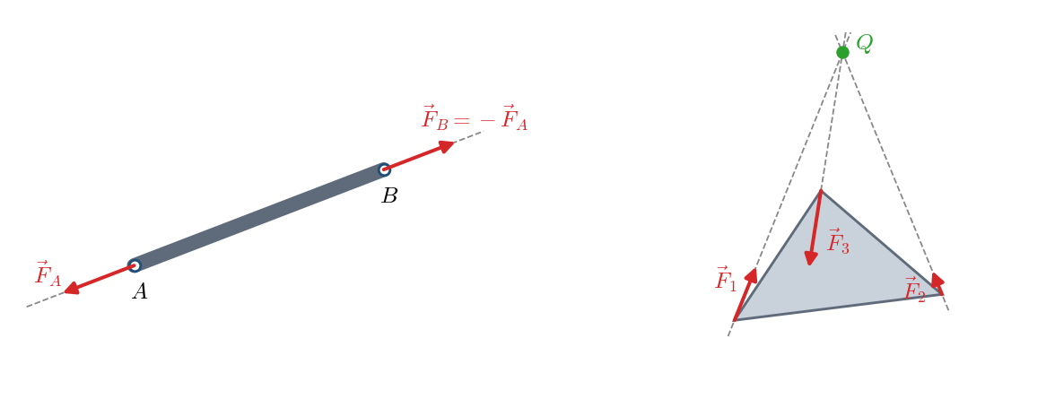
If only two forces act on a link (for instance, the reactions at its two joints, with no loads, no mass and no friction), both must have the same line of action (the line through their points of application), the same magnitude and opposite senses:
A massless connecting rod is the typical example: it works in tension or compression.
If three forces act on a link, their lines of action must meet at a single point (be concurrent), or be parallel; otherwise, the resultant of two of them would form a couple with the third one. Besides, they must form a closed triangle:
The strategy is to start with the two-force members, which give the lines of action of some reactions, and continue with the three-force members, whose point of concurrency gives the line of action of the third force.
Static analysis of the four-bar linkage#
Given: geometry, position and an external force \(\vec{P}_4\) on rocker 4. Unknowns: reactions at the four joints and the torque \(M_2\) to be applied to the crank for equilibrium.
Link 3 (coupler): it only receives forces at \(A\) and \(B\), so it is a two-force member: \(\vec{F}_{34}\) acts along \(AB\).
Link 4: it carries three forces: \(\vec{P}_4\) (known), \(\vec{F}_{34}\) (along \(AB\)) and \(\vec{F}_{14}\) (through \(O_4\)). The three meet at the intersection point \(Q\) of the lines of \(\vec{P}_4\) and \(AB\), so \(\vec{F}_{14}\) acts along \(O_4Q\). The force triangle \(\vec{P}_4 + \vec{F}_{34} + \vec{F}_{14} = \vec{0}\) gives their magnitudes.
Link 2: it receives \(\vec{F}_{32} = -\vec{F}_{23} = \vec{F}_{43} = -\vec{F}_{34}\) at \(A\) and \(\vec{F}_{12}\) at \(O_2\). For force equilibrium, \(\vec{F}_{12} = -\vec{F}_{32}\); these two parallel forces form a couple of value \(|\vec{F}_{32}|\cdot d_2\) (\(d_2\), distance from \(O_2\) to line \(AB\)), which balances the torque \(M_2\).
Ground: it receives \(\vec{F}_{21}\) and \(\vec{F}_{41}\), whose sum equals \(\vec{P}_4\), and a shaking moment that its anchors must withstand.
Example Example 3.5: Graphical static analysis of a four-bar linkage works out this case with numbers.
Static analysis of the slider-crank mechanism#
Given: dimensions, position and force \(\vec{F}_4\) on the piston (for instance, the gas force). Unknowns: reactions at each joint and the torque \(M_2\) the crankshaft can overcome.
Link 3 (connecting rod): two-force member, \(\vec{F}_{43} = -\vec{F}_{23}\), both along \(AB\).
Link 4 (piston): \(\vec{F}_{14} + \vec{F}_{34} + \vec{F}_4 = \vec{0}\), with \(\vec{F}_{14}\) perpendicular to the guide and \(\vec{F}_{34}\) parallel to \(AB\): a force triangle gives both magnitudes. (The moment equation holds for any value if all forces go through \(B\).)
Link 2 (crank): \(\vec{F}_{12} = -\vec{F}_{32}\) and \(M_2 = |\vec{F}_{32}|\cdot d_2\).
Ground: the reactions \(\vec{F}_{41}\) and \(\vec{F}_{21}\), together with the gas reaction on the cylinder head (\(-\vec{F}_4\)), produce a shaking moment of value \(|\vec{F}_{41}|\cdot \overline{O_2B}\).
Inertia loads with graphical methods#
With D’Alembert’s principle, the dynamic analysis is solved just like the static one, adding the inertia force of each link. To give each link “one more force”, its inertia force and torque are replaced by the equivalent inertia force \(\vec{J}'_i\), shifted \(h_i = I_{G_i}|\alpha_i| / (m_i|\vec{a}_{G_i}|)\) (see D’Alembert’s principle).
The procedure is:
Get the inertia forces and torques of each link: \(\vec{J}_i = -m_i\vec{a}_{G_i}\), \(M_{G_i} = -I_{G_i}\alpha_i\). The accelerations are taken from the acceleration polygon.
Get the equivalent inertia force of each link: \(\vec{J}'_i = \vec{J}_i\) shifted \(h_i\).
Solve the equilibrium of each link as in the static case. On the input link, a torque not balanced by the other links appears, the accelerating torque, which the motor must supply.
Simple case: a single link with mass#
If only one link has mass (or only one has significant mass), the others are still two-force members and the problem is the same as the static one, with \(\vec{J}'\) instead of the external load. The construction below shows it step by step for a four-bar linkage in which only the rocker has mass (Example 3.6: Inertia forces in a four-bar linkage (graphical method)). You can drag the crank to see how the solution changes with the position:
General case: all links with mass#
If the coupler also has mass, it is no longer a two-force member, and no link carries just three forces. For the four-bar linkage, we proceed as follows:
Link 4: \(\vec{F}_{14} + \vec{F}_{34} + \vec{J}'_4 = \vec{0}\). \(\vec{F}_{34}\) (and \(\vec{J}'_4\)) are split into a component perpendicular to the link and another one along it, \(\vec{F}_{34} = \vec{F}^{\perp}_{34} + \vec{F}^{\parallel}_{34}\). Taking moments about \(O_4\), the parallel component has no moment, and:
where \(G'_4\) is the point where the line of action of \(\vec{J}'_4\) crosses the link.
Link 3: likewise, taking moments about \(A\):
Joining at \(B\): since \(\vec{F}_{43} = -\vec{F}_{34}\), both perpendicular components at \(B\) are known, as well as the lines of action of both parallel ones (each along its own link). A polygon with \(\vec{F}^{\perp}_{43} + \vec{F}^{\parallel}_{43} = -(\vec{F}^{\perp}_{34} + \vec{F}^{\parallel}_{34})\) gives the magnitudes of the parallel components and, with them, the full \(\vec{F}_{34}\).
Closing: the polygon \(\vec{F}_{14} + \vec{F}_{34} + \vec{J}'_4 = \vec{0}\) gives \(\vec{F}_{14}\), and the polygon \(\vec{F}_{23} + \vec{F}_{43} + \vec{J}'_3 = \vec{0}\) gives \(\vec{F}_{23}\).
Link 2: \(\vec{F}_{12} + \vec{F}_{32} + \vec{J}'_2 = \vec{0}\) and, taking moments about \(O_2\), the accelerating torque \(M_2 = |\vec{F}_{32}|\, d_{32} + |\vec{J}'_2|\, d_2\) (with the sign of each moment).
In the slider-crank mechanism, the piston translates (\(\alpha_4 = 0\)) and its inertia force \(\vec{J}_4 = -m_4\vec{a}_B\) goes through \(B\); the reaction at \(A\) on the connecting rod is split into components perpendicular and parallel to \(AB\), and moments are taken about \(B\).
Alternatively, the superposition principle can be applied: solve the mechanism with the inertia of a single link at a time (with the other links as two-force members) and add up. The complete example of the six-bar mechanism (Example 3.7: Transfer mechanism (complete analysis)) is solved graphically by analyzing the links in a suitable order.
Slider-crank with only the slider having mass#
Another very common case: crank and connecting rod of negligible mass and a slider of mass \(M\) (Example 3.4: Slider-crank with the mass at the slider). The slider translates, so it only has an inertia force; the rod is a two-force member and the slider, a three-force member:
Complete kinetostatic analysis#
By the superposition principle, the total forces on each link are the sum of those from the static analysis (external loads) and those from the dynamic analysis (inertia loads). In a reciprocating engine, for example:
The connecting rod works in tension or compression under the sum of the gas force and the inertia loads.
The crank receives a torque: the effective engine torque is the difference between the torque produced by the gas (static analysis) and the accelerating torque needed to move the masses (dynamic analysis). Depending on the position, inertia makes the effective torque larger or smaller than the one produced by the gas.
The frame suffers a shaking moment and a resultant force that the engine mounts must absorb.